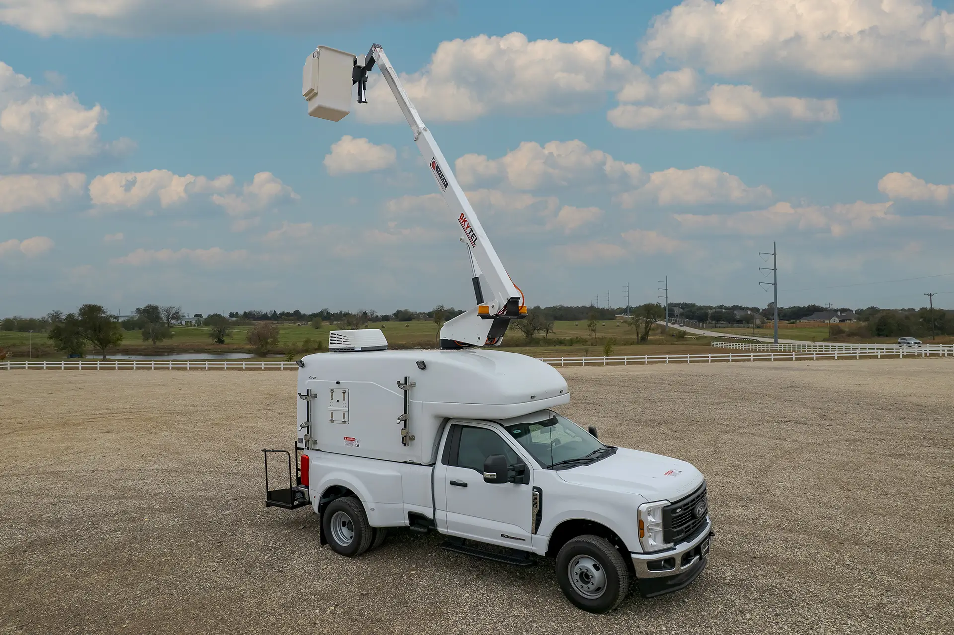
SkyTel
Reach Higher. Work Smarter.
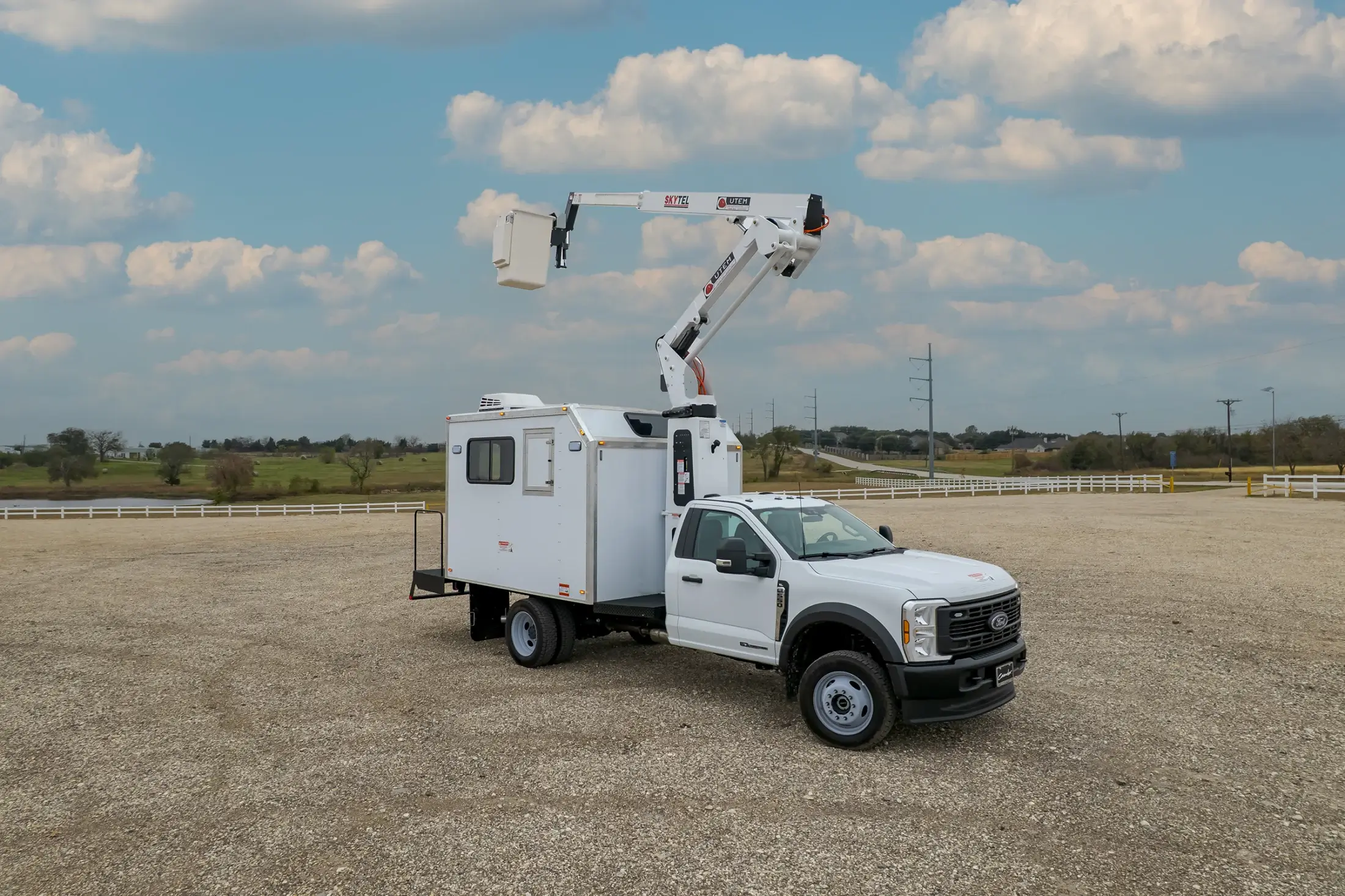
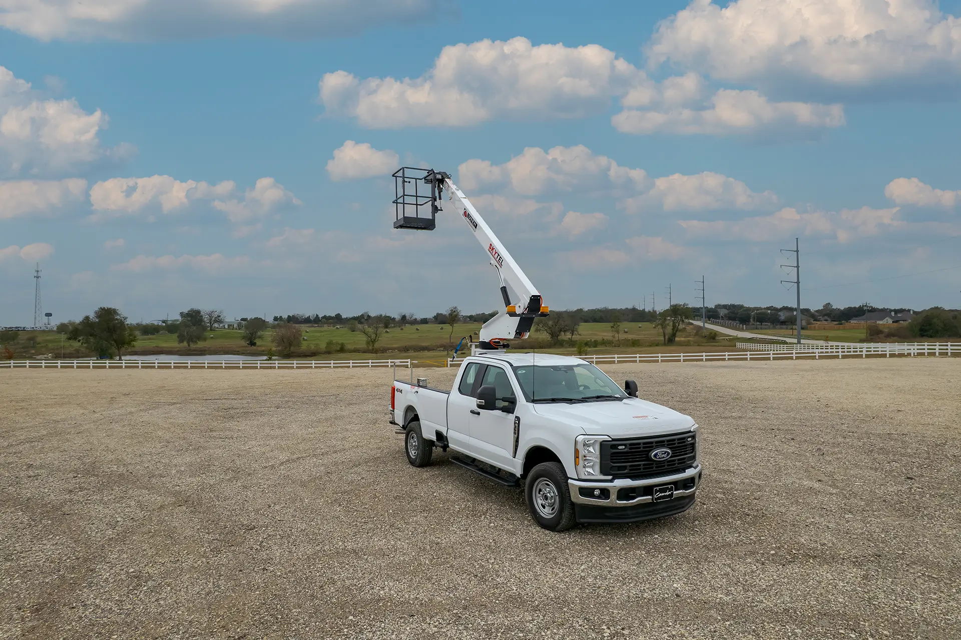
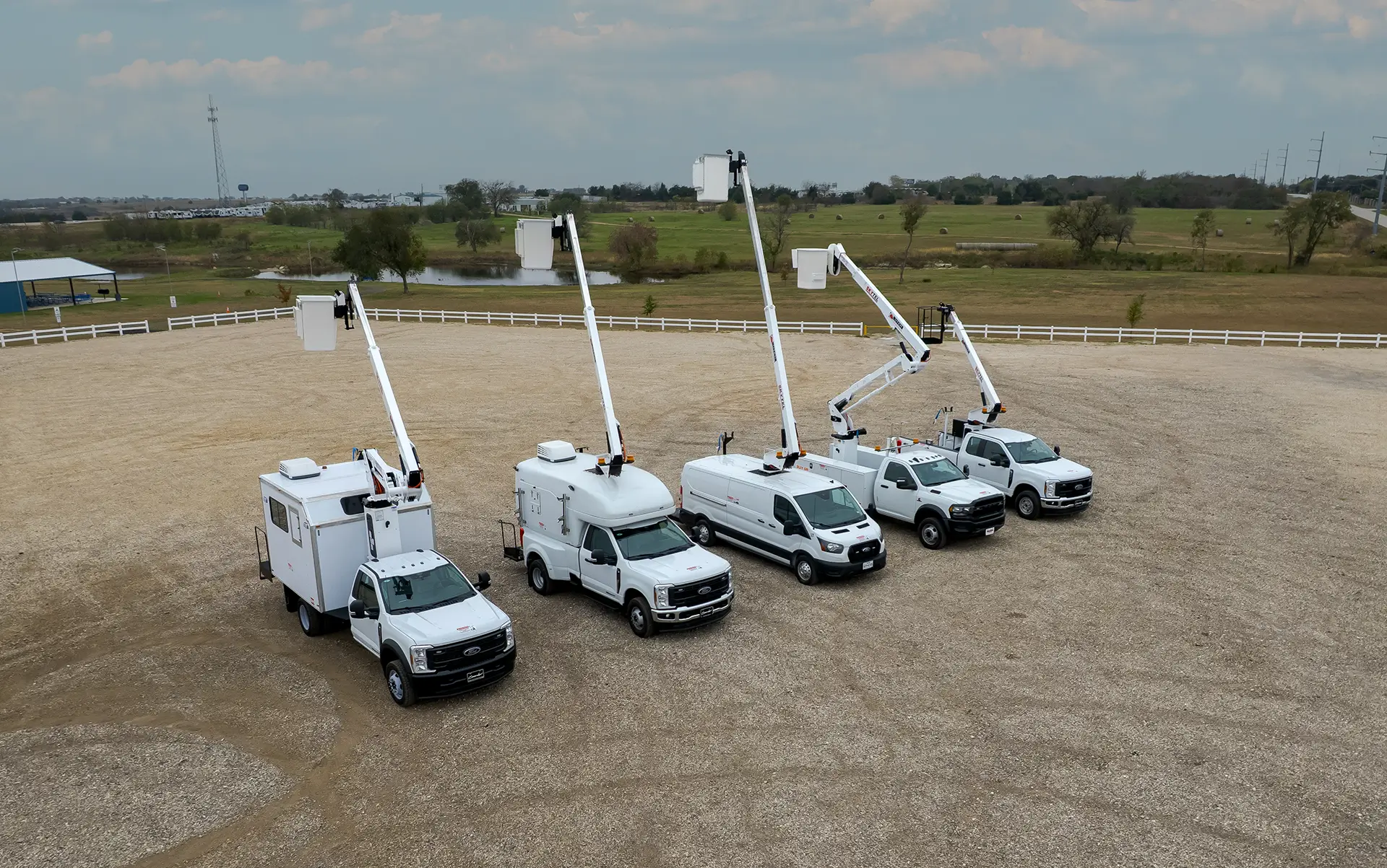
The UTEM SkyTel series includes three telescopic and telescopic-articulated models—SkyTel 35, SkyTel 41, and SkyTel 46—built for crews that need extra height, smooth maneuverability, and reliable lift performance in utility, telecom, construction, and municipal environments. With insulated and non-insulated options, SkyTel gives you safe, stable reach with the precision needed for real-world jobs.
Whether your team needs compact height, mid-range flexibility, or maximum vertical reach, the SkyTel lineup delivers a telescopic aerial device built for long days and tough conditions.
Working Height:
34 ft – 45 ft 8 in
(model dependent)
Horizontal Reach:
20 ft 9 in – 27 ft 9 in
Basket Capacity:
350 – 400 lbs
* dimensions vary according to model number and options
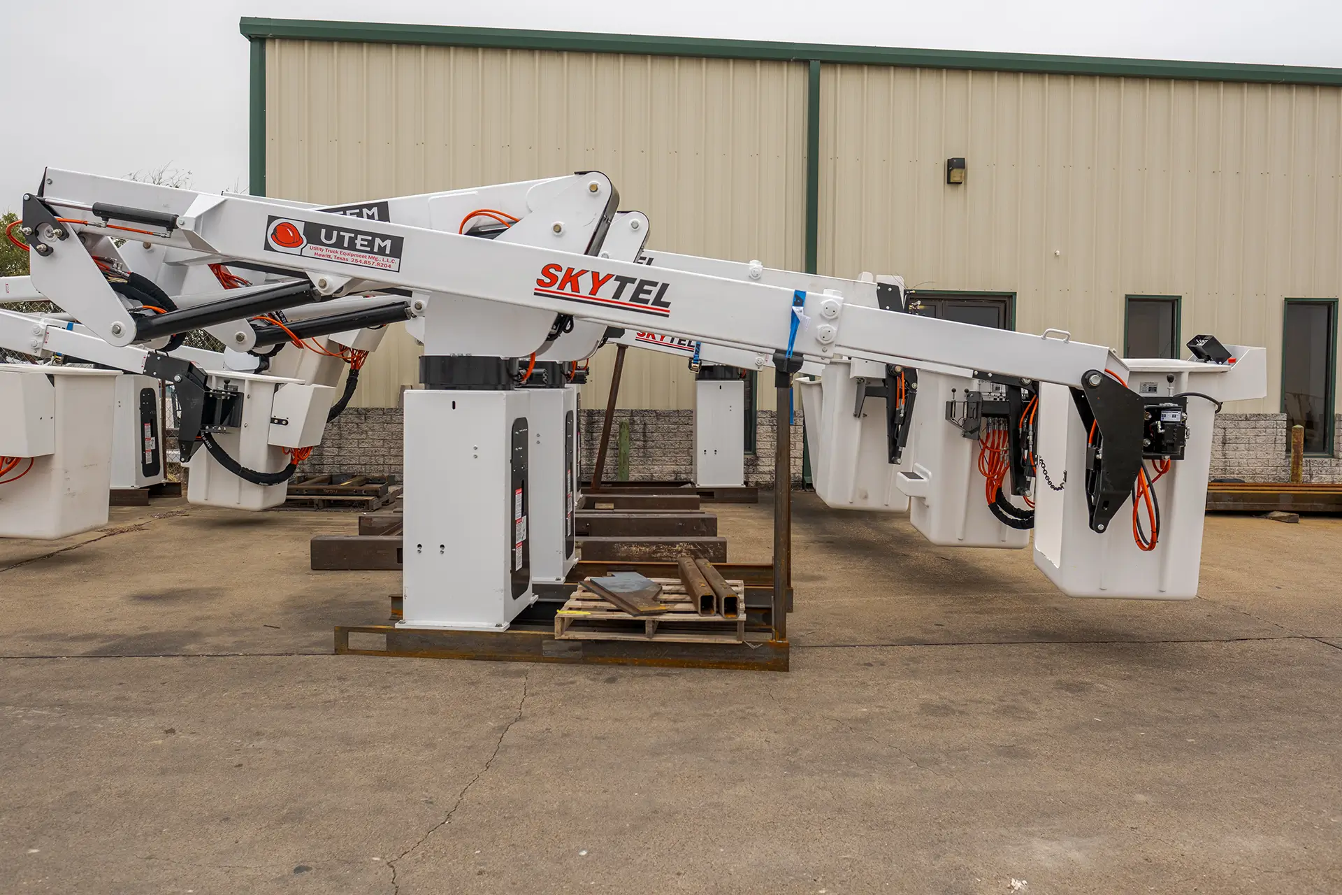
SkyTel Features
- Three available models: SkyTel 35, SkyTel 41, SkyTel 46
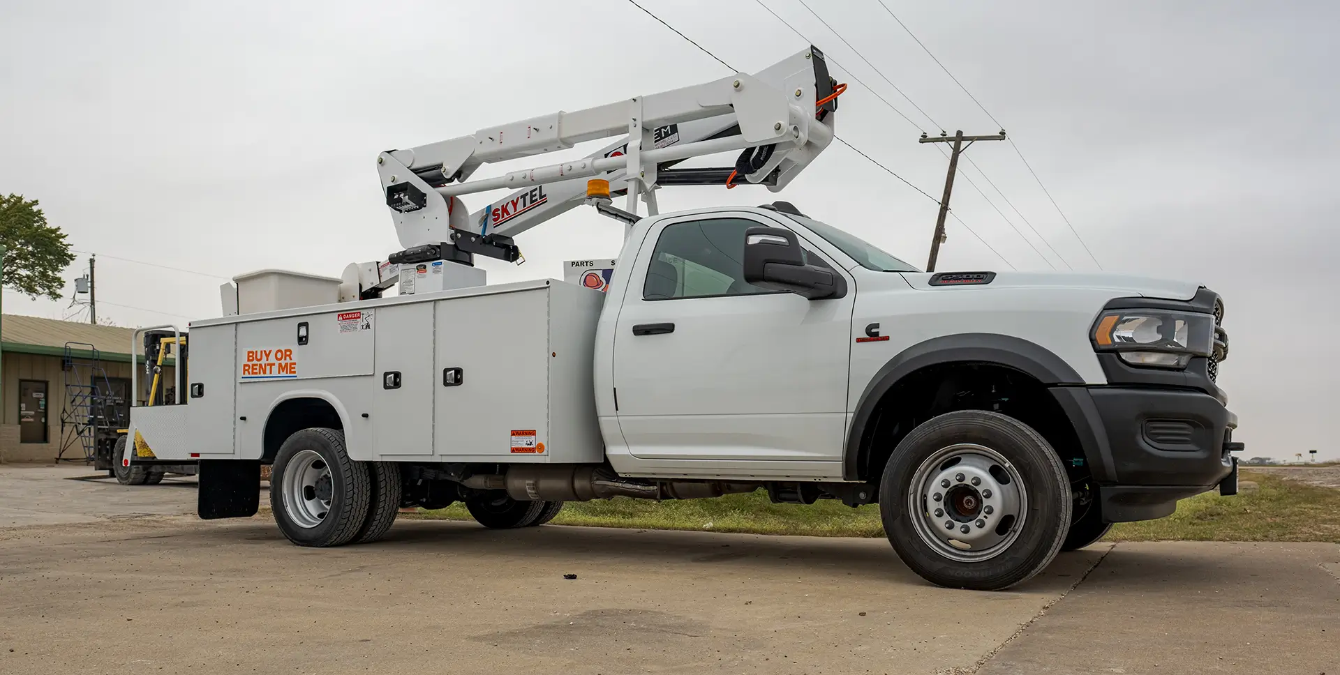
- Telescopic or telescopic-articulated boom configurations
- Insulated and non-insulated options
- Smooth hydraulic controls for precise positioning
- Upper and lower control stations
- ANSI-compliant fall-arrest anchor
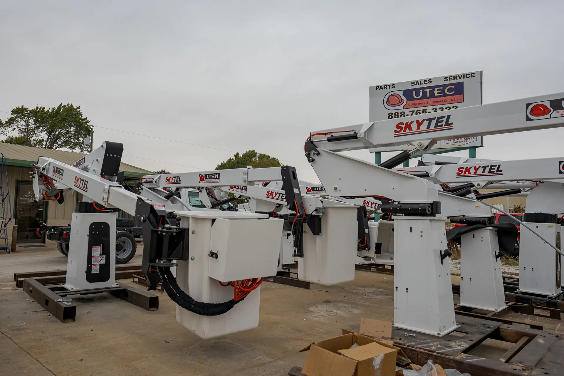
- High-strength boom construction
- Clean hose routing for simplified maintenance
- Reliable operation across utility, telecom, and construction sites
- Compatible with multiple chassis platforms
Applications
Designed for teams that need height, control, and dependable performance.
REQUIREMENTS AND SPECIFICATIONS
SkyTel 35 Specifications
Side Mounted Basket Specifications
| Models | UTLI35A (Non-Insulated) | UTLI35B (Insulated) |
|---|---|---|
| Basket Bottom Height 1 | 29 ft. (8.84m) | 29 ft. (8.84m) |
| Working Height 1 | 34 ft. (10.36m) | 34 ft. (10.36m) |
| Standard Basket Capacity | 300 lbs. (136kg) | 300 lbs. (136kg) |
| Maximum Basket Capacity | 400 lbs. (181kg) | 400 lbs. (181kg) |
| Maximum Horizontal Reach | 22 ft. 9 in. (6.93m) | 22 ft. 9 in. (6.93m) |
| Boom Articulation | -140 to 780 | -140 to 780 |
| Boom Extension | n/a | 108 in (3.05m) |
| Insulation Gap Fully Retracted | n/a | 30 in (0.76m) |
| Insulation Gap Extended | 108 in. (3.05m) | 108 in. (3.05m) |
| Stowed Travel Height 1 | 10 ft. 2 in. (3.10m) | 10 ft. 2 in. (3.10m) |
| Electrical System Voltage | 12VDC | 12VDC |
| Rotation | 5400 Non-Continuous | 5400 Non-Continuous |
| Hydraulic System Operating Pressure | 2200 PSI (155kg/cm2) | 2200 PSI (155kg/cm2) |
| Unit Weight 2 | 1650 lbs. (748kg) | 1549 lbs. (702kg) |
1. Based on 36 in (0.91m) chassis frame height.
2. Configured with “HE” hydraulic power package and pedestal main frame.
Add 300 lbs. (136kg) for batteries on units with optional “EH” or “DP” hydraulic power package.
Add 300 lbs. (136kg) for UVN35A SkyVan units with pedestal main frame.
Add 100 lbs. (45kg) for units with optional bridge main frame.
End Mounted Basket Specifications
| Models | UTLN35A (Non-Insulated) | UTLN35A (Insulated) |
|---|---|---|
| Basket Bottom Height 1 | 29 ft. (8.84m) | 29 ft. (8.84m) |
| Working Height 1 | 34 ft. (10.36m) | 34 ft. (10.36m) |
| Standard Basket Capacity | 300 lbs. (136kg) | 300 lbs. (136kg) |
| Maximum Basket Capacity | 400 lbs. (181kg) | 400 lbs. (181kg) |
| Maximum Horizontal Reach | 22 ft. 9 in. (6.93m) | 22 ft. 9 in. (6.93m) |
| Boom Articulation | -140 to 780 | -140 to 780 |
| Boom Extension | n/a | 108 in (3.05m) |
| Insulation Gap Fully Retracted | n/a | 30 in (0.76m) |
| Insulation Gap Extended | 108 in. (3.05m) | 108 in. (3.05m) |
| Stowed Travel Height 1 | 10 ft. 2 in. (3.10m) | 10 ft. 2 in. (3.10m) |
| Electrical System Voltage | 12VDC | 12VDC |
| Rotation | 5400 Non-Continuous | 5400 Non-Continuous |
| Hydraulic System Operating Pressure | 2200 PSI (155kg/cm2) | 2200 PSI (155kg/cm2) |
| Unit Weight 2 | 1650 lbs. (748kg) | 1549 lbs. (702kg) |
1. Based on 36 in (0.91m) chassis frame height.
2. Configured with “HE” hydraulic power package and pedestal main frame.
Add 300 lbs. (136kg) for batteries on units with optional “EH” or “DP” hydraulic power package.
Add 300 lbs. (136kg) for UVN35A SkyVan units with pedestal main frame.
Add 100 lbs. (45kg) for units with optional bridge main frame.
Vehicle Requirements
| Requirement | Minimum | Recommended |
|---|---|---|
| GVWR2,3 | 10,100 lbs. (4581kg) | 14,500 lbs. (6577kg) |
| Front GAWR2,4 | 4,000 lbs. (1814kg) | 5,000 lbs. (2268kg) |
| Rear GAWR2,4 | 7,500 lbs. (3402kg) | 9,500 lbs. (4309kg) |
| Cab to Rear Axle | 60 in. (1.52m) | 84 in. (2.13m) |
| Frame Section Modulus | 5.4in.^3 (88cm^3) | 5.4in.^3 (88cm^3) |
| RBM of Frame | 195,000in.-lbs. (22035N-m) | 195,000in.-lbs. (22035N-m) |
1. Based on 25.5 in.(0.65m) chassis frame height.
2. Actual curb weight for stability and the required GVWR and GAWR can vary significantly with vehicle stiffness, suspension stiffness, vehicle wheelbase, aerial lift mounting location, body, accessories, ballast (if required), platform capacity and desired payload. Actual weight for stability must be determined by testing in accordance with the ANSI A92.2 standard.
3. GVWR means gross vehicle weight rating.
4. GAWR means gross axle weight rating.
* Based on minimum specifications
SkyTel 41 Specifications
Side Mounted Basket Specifications
| Models | UTLI41 (Non-Insulated) | UTLI41A (Insulated) |
|---|---|---|
| Basket Bottom Height 1 | 36 ft. 9 in. (11.19m) | 36 ft. 9 in. (11.19m) |
| Working Height 1 | 41 ft. 9 in. (12.72m) | 41 ft. 9 in. (12.72m) |
| Standard Basket Capacity | 300 lbs. (136kg) | 300 lbs. (136kg) |
| Maximum Basket Capacity | 350 lbs. (159kg) | 400 lbs. (181kg) |
| Maximum Horizontal Reach | 28 ft.2 in.(8.58m) | 27 ft.9 in.(8.46m) |
| Lower Boom Articulation | -60 to 900 (Lower Boom Articulation) | -60 to 900 (Lower Boom Articulation) |
| Upper Boom Articulation | -140 to 780 (Upper Boom Articulation) | -140 to 780 (Upper Boom Articulation) |
| Upper Boom Extension | 108 in. (2.74m) (Upper Boom Extension) | 108 in. (2.74m) (Upper Boom Extension) |
| Insulation Gap Fully Retracted | n/a | 30 in. (0.76m) (Insulation Gap Fully Retracted) |
| Insulation Gap Extended | n/a | 42 in. (1.07m) (Insulation Gap Extended) |
| Stowed Travel Height1 | 10 ft. 2 in. (3.10m) (Stowed Travel Height) | 10 ft. 2 in. (3.10m) (Stowed Travel Height) |
| Electrical System Voltage | 12VDC (Electrical System Voltage) | 12VDC (Electrical System Voltage) |
| Rotation | 5400 (Rotation, Non-Continuous) | 5400 (Rotation, Non-Continuous) |
| Hydraulic System Operating Pressure | 2200PSI (155kg/cm2) | 2500 PSI (176kg/cm2) |
| Unit Weight | 2324 lbs.(1054.1kg) | 2339 lbs.(1015.2kg) |
1. Based on 36 in (0.91m) chassis frame height.
Chassis Requirements
| Requirement | Minimum | Recommended |
|---|---|---|
| GVWR2,3 | 15,000 lbs. (6804kg) | 15,000 lbs. (6804kg) |
| Front GAWR2,4 | 5,000 lbs. (2268kg) | 6,000 lbs. (2722kg) |
| Rear GAWR2,4 | 11,000 lbs. (4990kg) | 11,000 lbs. (4990kg) |
| Cab to Rear Axle | 60 inches | 84 in. (2.13m) |
| Frame Section Modulus | 8.0 cubic inches | 8.0 in.3 (131cm3) |
| RBM of Frame | 280,000 in.-lbs. | 280,000 in.-lbs. (31640N-m) |
1. Based on 25.5 in.(0.65m) chassis frame height.
2. Actual curb weight for stability and the required GVWR and GAWR can vary significantly with vehicle stiffness, suspension stiffness, vehicle wheelbase, aerial lift mounting location, body, accessories, ballast (if required), platform capacity and desired payload. Actual weight for stability must be determined by testing in accordance with the ANSI A92.2 standard.
3. GVWR means gross vehicle weight rating.
4. GAWR means gross axle weight rating.
End Mounted Basket Specifications
| Model | UTLI41 (Non-Insulated) | UTLI41A (Insulated) |
|---|---|---|
| Basket Bottom Height 1 | 36 ft. 9 in. (11.19m) | 36 ft. 9 in. (11.19m) |
| Working Height 1 | 41 ft. 9 in. (12.72m) | 41 ft. 9 in. (12.72m) |
| Standard Basket Capacity | 300 lbs. (136kg) | 300 lbs. (136kg) |
| Maximum Basket Capacity | 350 lbs. (159kg) | 400 lbs. (181kg) |
| Maximum Horizontal Reach | 28 ft. 2 in. (8.58m) | 27 ft. 9 in. (8.46m) |
| Lower Boom Articulation | -60 to 900 (Lower Boom Articulation) | -60 to 900 (Lower Boom Articulation) |
| Upper Boom Articulation | -140 to 780 (Upper Boom Articulation) | -140 to 780 (Upper Boom Articulation) |
| Upper Boom Extension | 108 in. (2.74m) (Upper Boom Extension) | 108 in. (2.74m) (Upper Boom Extension) |
| Insulation Gap Fully Retracted | n/a | 30 in. (0.76m) (Insulation Gap Fully Retracted) |
| Insulation Gap Extended | n/a | 42 in. (1.07m) (Insulation Gap Extended) |
| Stowed Travel Height 1 | 10 ft. 2 in. (3.10m) (Stowed Travel Height) | 10 ft. 2 in. (3.10m) (Stowed Travel Height) |
| Electrical System Voltage | 12VDC (Electrical System Voltage) | 12VDC (Electrical System Voltage) |
| Rotation | 5400 (Rotation, Non-Continuous) | 5400 (Rotation, Non-Continuous) |
| Hydraulic System Operating Pressure | 2200PSI (155kg/cm2) | 2500 PSI (176kg/cm2) |
| Unit Weight | 2374 lbs. (1076.1kg) | 2333 lbs. (1058.2kg) |
1. Based on 36 in (0.91m) chassis frame height.
* Based on minimum specifications
SkyTel 46 Specifications
Side Mounted Specifications
| Model | UTLI46 (Non-Insulated) | UTLI46 (Insulated) |
|---|---|---|
| Basket Bottom Height 1 | 40 ft.8 in.(12.40m) | 40 ft.8 in.(12.40m) |
| Working Height 1 | 45 ft.8 in.(13.92m) | 45 ft.8 in.(13.92m) |
| Standard Basket Capacity | 300 lbs.(136kg) | 300 lbs.(136kg) |
| Maximum Basket Capacity | 400 lbs.(181kg) | 400 lbs.(181kg) |
| Maximum Horizontal Reach | 25 ft.8 in.(7.84m) | 25 ft.8 in.(7.84m) |
| Lower Boom Articulation | -40 to 900 | -40 to 900 |
| Upper Boom Articulation | -140 to 780 | -140 to 780 |
| Upper Boom Extension | 108 in.(2.74m) | 108 in.(2.74m) |
| Insulation Gap Fully Retracted | n/a | 30 in (0.76m) |
| Insulation Gap Extended | n/a | 42 in (1.07m) |
| Stowed Travel Height 1 | 10 ft.2 in (3.10m) | 10 ft.2 in (3.10m) |
| Electrical System Voltage | 12 VDC | 12 VDC |
| Rotation | 5400 Non-Continuous | 5400 Non-Continuous |
| Hydraulic System Operating Pressure | 2500 PSI(176kg/cm2) | 2500 PSI(176kg/cm2) |
| Unit Weight | 2430 lbs.(1102.2kg) | 2410 lbs.(1093.2kg) |
1. Based on 36 in (0.91m) chassis frame height.
Chassis Requirements
| Requirement | Minimum | Recommended |
|---|---|---|
| GVWR2,3 | 15,000 lbs. (6804kg) | 15,000 lbs. (6804kg) |
| Front GAWR2,4 | 5,000 lbs. (2268kg) | 6,000 lbs. (2722kg) |
| Rear GAWR2,4 | 11,000 lbs. (4990kg) | 11,000 lbs. (4990kg) |
| Cab to Rear Axle | 60 inches | 84 in. (2.13m) |
| Frame Section Modulus | 8.0 cubic inches | 8.0 in.3 (131cm3) |
| RBM of Frame | 280,000 in.-lbs. | 280,000 in.-lbs. (31640N-m) |
1. Based on 25.5 in.(0.65m) chassis frame height.
2. Actual curb weight for stability and the required GVWR and GAWR can vary significantly with vehicle stiffness, suspension stiffness, vehicle wheelbase, aerial lift mounting location, body, accessories, ballast (if required), platform capacity and desired payload. Actual weight for stability must be determined by testing in accordance with the ANSI A92.2 standard.
3. GVWR means gross vehicle weight rating.
4. GAWR means gross axle weight rating.
End Mounted Basket Specifications
| Models | UTLI46 (Non-Insulated) | UTLI46A (Insulated) |
|---|---|---|
| Basket Bottom Height 1 | 40 ft. 9 in. (12.41 meters) | 40 ft. 9 in. (12.41m) |
| Working Height 1 | 45 ft. 9 in. (13.94 meters) | 45 ft. 9 in. (13.94m) |
| Standard Basket Capacity | 300 lbs. (136 kg) | 300 lbs. (136kg) |
| Maximum Basket Capacity | 350 lbs. (159 kg) | 400 lbs. (181kg) |
| Maximum Horizontal Reach | 27 ft. 8 in. (8.43 meters) | 27 ft.9 in.(8.46m) |
| Lower Boom Articulation | -40 to 90 degrees | -40 to 90 degrees |
| Upper Boom Articulation | -140 to 78 degrees | -140 to 78 degrees |
| Upper Boom Extension | 108 in. (2.74 meters) | 108 in. (2.74 meters) |
| Insulation Gap Fully Retracted | n/a | 30 in. (0.76m) |
| Insulation Gap Extended | n/a | 42 in. (1.07m) |
| Stowed Travel Height 1 | 10 ft. 2 in. (3.10 meters) (Stowed Travel Height) | 10 ft. 2 in. (3.10m) |
| Electrical System Voltage | 12VDC (Electrical System Voltage) | 12VDC |
| Rotation | 5400 (Non-Continuous) | 5400 (Non-Continuous) |
| Hydraulic System Operating Pressure | 2500 PSI (176 kg/cm2) | 2500 PSI (176kg/cm2) |
| Unit Weight | 2480 lbs. (1124.9 kg) | 2445 lbs.(1109.0kg) |
1. Based on 36 in (0.91m) chassis frame height.
* Based on minimum specifications